
A torque converter is a hydraulic fluid system coupling used to connect power from one or more systems or motors to a driveshaft or some output shaft. It takes the place of a clutch and, within specific operating speed ranges, increases input torque, providing a reduction clutch’s equivalent.
Uses
Torque converters are mainly found in automotive automatic transmissions and used in marine propulsion systems and other industrial equipment tools.
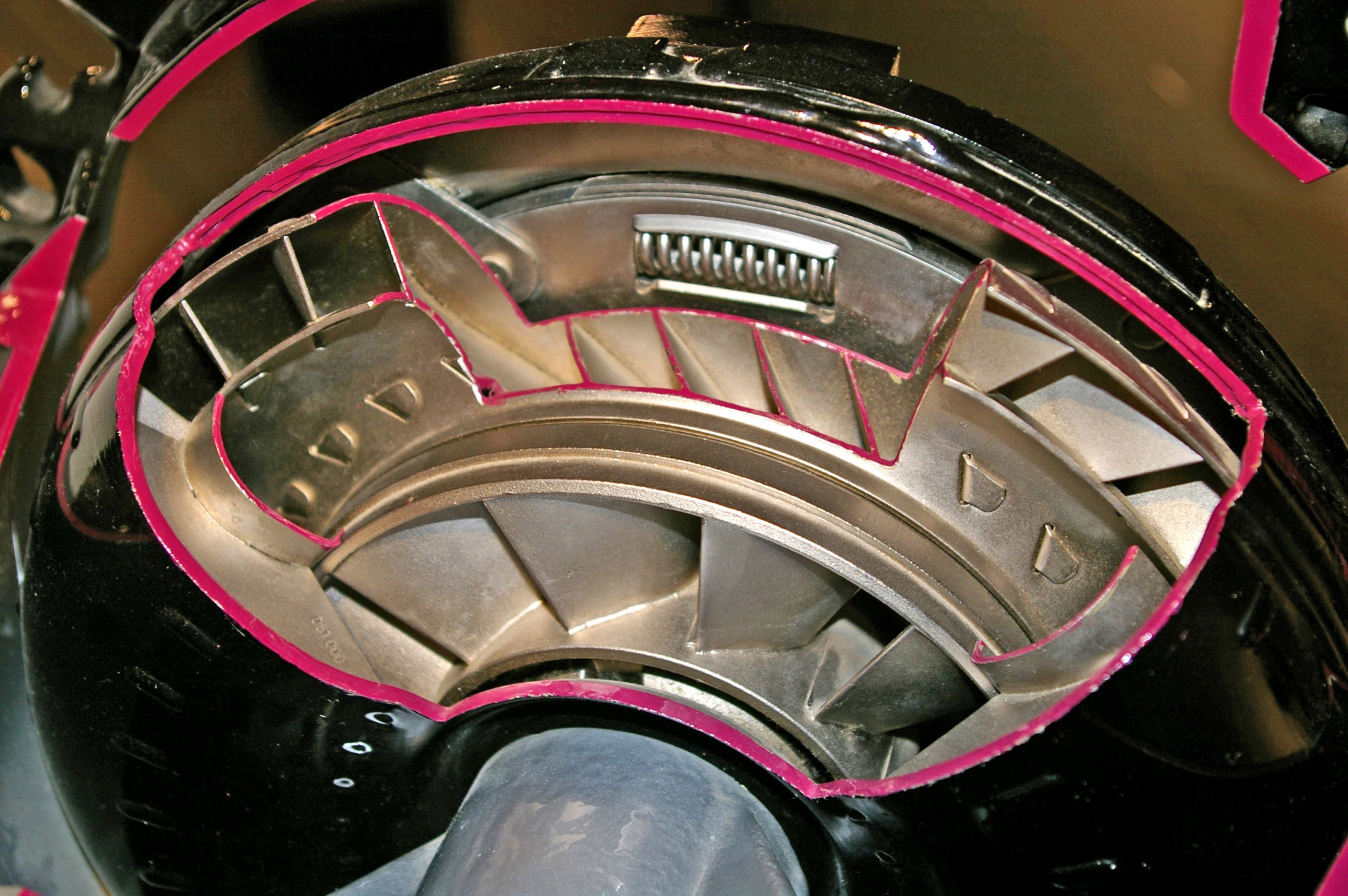
A torque converter, like any fluid coupling, is a secured chamber filled with hydraulic fluid containing a pump driven by the engine and a turbine connected to an output shaft. The impeller is a toroid disc attached to the engine’s crankshaft (or output shaft of the motor or other power source).
How it works
When the system or power source is running, it turns the impeller at the same speed. The rotation of the radial area on the pump’s inner surface imparts a centrifugal radial flow to the liquid in the converter, which causes hydraulic fluid to strike the turbine’s outer edges.
The radial chambers on the turbine’s surface transmit the fluid centripetally’s angular momentum, reversing its direction and exerting a twisting force-torque on the turbine plates that causes it to rotate the same location as the impeller. The liquid exits the center of the turbine and back to the impeller to start the cycle again.
Because some of the energy imparted to the liquid is lost to friction (raising the fluid temperature rather than causing motion within it), the turbine always slips (rotates slower than the impeller), particularly at very low speeds. Suppose the impeller’s speed is deficient, such as at average speed for an automobile engine. In that case, the torque released on the turbine output shaft will not be enough to overcome the shaft’s inertia, releasing the shaft to remain stationary without stalling the engine and eliminating the need for de-clutching.
As engine speed increases, the impeller and the turbine’s speed become nearly the same. Because the turbine is spinning faster than it can exit its radial chambers, the exiting fluid’s net angular momentum is in the same direction as the turbine’s rotation, rather than opposing it as the impeller near this speed, the torque converter repair multiplication is given by the stator decreases. At that critical speed, the fluid strikes the back of the stator levels, causing the stator to freewheel so that it will not give problems with the return flow of fluid.
Some torque converters, such as specific versions of General Motors’s TurboHydramatic, have a variable-pitch stator that can alter the stator blades’ angle between two or more positions depending on engine speed and throttle position, usually utilizing a solenoid that moves the blades to a higher angle when engaged.
Some torque converters use multiple stators and multiple turbines to provide a broader range of torque converter repair addition. Such multiple-element converters are more common in applications than in automotive transmissions.
Torque Converter Maintenance And Troubleshooting
Check the following as outlined in the maintenance manual:
- (unit must be disassembled)
-
- Turbine to stator interference
- Impeller to stator interference
- Stator one-way clutch lock -. up torque
- Troubleshooting with the unit in place:
- . Oil level
- Output speed (stall)
- Charging pump pressure
- alter’ pressure
- Leakage
- Screen for metal particles


Leave a Reply